Synchronisation and SMPTE timecode (time code)
 This document is a description (mainly technical, but not requiring extensive prior knowledge) of the SMPTE time-code synchronization system, especially the Bi-Phase Mark "LTC" timecode sync tone which can be recorded onto the audio track of a video tape or onto an audio tape. Other time code variants, such as VITC time-code are also mentioned. Some supporting information on the related subjects of colour television standards and field sequences is included. There is also a concise description of the binary coded decimal (BCD) representation as used in the SMPTE (or EBU) timecode (time code) data word.
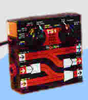
My original reason for exploring this subject technically was to develop a low cost MIDI tape sync unit, which was a frequent customer request, and a logical addition to our range of electronic music gadgets. Our Time Code tape sync unit, which supported SMPTE (including Drop Frame format) and MIDI Time Code, was called the TS1 and was for over a decade a successful and highly-respected product.
Synchronisation systems
When you require pieces of audio, video, or music technology equipment (eg. tape recorder and sequencer) to work together, you may need some means to make sure that they play in time with each other. This is called 'synchronisation' or 'synchronization', which gets shortened to 'sync' or even 'synch'.
A magnetic tape-recorder track is the region of the tape that is scanned by one recording head element. It can, for example, carry an audio signal, that is an electronic analogue of a stream of sound. In order to use an audio track to record sync information, the information must be encoded into an audio-compatible signal, called a sync tone. An audio tape track on which a sync tone has been recorded is called a 'stripe'. It is desirable that the synchronised devices can join in wherever you start up the sync tone, even if it is not at the beginning of the stripe; this is called 'chasing'. The SMPTE/EBU timecode standard defines the predominant internationally accepted standard for a sync tone and it allows devices to 'chase' or locate to a precise position.
![]() In music technology applications, with equipment which is not timecode compatible, you may be able to use a tape sync unit by way of a tempo-relative stripe system. Examples of such systems are traditional FSK (Frequency Shift Key) and the Philip Rees proprietary FSKplus format.
In music technology applications, with equipment which is not timecode compatible, you may be able to use a tape sync unit by way of a tempo-relative stripe system. Examples of such systems are traditional FSK (Frequency Shift Key) and the Philip Rees proprietary FSKplus format.
The SMPTE/EBU timecode standard
Until the advent of video recording, there was mechanical sound to film synchronisation. This mainly relied on sprockets (a row of neat holes) in the film and in special sprocketed recording tape. Relative timing adjustments could be made by slipping sprocket holes. The same sprocket holes were used to maintain synchronisation. Video tape hasn't got any sprocket holes, so when video arrived an electronic equivalent was needed to take the place of mechanical methods of synchronisation.
 In 1967, The US Society of Motion Picture and Television Engineers introduced that which we call SMPTE ("simpty") time code. The audio sync tone version of SMPTE is called linear or longitudinal time code or LTC. By the way, there are also versions of timecode which can be inserted into a video signal or sent via a MIDI connection.
On the former website tvhandbook.com, a Broadcast History Timeline had this entry for the year of 1969: "SMPTE timecode established to end the chaos of incompatible time codes for various editing machines".
The original uses of SMPTE timecode include accurate video editing and synchronising film sound-tracks. The timing data in SMPTE takes the form of an eight digit twenty-four hour clock. The count consists of 0 to 59 seconds, 0 to 59 minutes and 0 to 23 hours. The second is subdivided into a number of frames, which may be varied to match the various frame-rates used around the world. The frame-rate is the number of times a second that the picture is updated so as to give the illusion of continuous movement.
Frame-rate formats
 There are four standard frame-rate formats: The SMPTE frame-rate of thirty frames per second (fps) is often used for audio in America. It is used with the Sony 1630 format for CD mastering. It has its origins in the obsolete American mono television standard. The American colour television standard has a slightly different frame-rate of about 29.97 fps. This is accommodated by the SMPTE format known as thirty Drop Frame and is required for video work in America, Japan and generally the 60 Hz (mains frequency), NTSC (television standard) world. The number of frames in each second is not an integer, so an approximation is used; it is based on 30 fps, but two frames counts are dropped (skipped) at the start of every minute, except for every tenth minute (the minutes of every hour in which no frames are dropped are minutes 1, 11, 21, 31, 41 and 51). The EBU (European Broadcasting Union) standard of 25 fps is used throughout Europe, Australia and wherever the mains frequency is 50 Hz and the colour TV system is PAL or SECAM. The remaining rate of 24 fps is required for film work, it is rarely used for audio.
In audio post-production, SMPTE has been adopted for machine synchronisation and as a reference of tape position. Essentially, the choice of frame rate for audio work is usually arbitrary.
The modulation scheme of SMPTE LTC
 A bit is a binary digit (which can take only the value 0 or 1). The value of a bit is often represented by the 'off' and 'on' states of an electronic switch. When the sequence of binary digits must pass through a channel designed for analogue audio signals the 'on' and 'off' states ('phase') cannot be reliably distinguished. However, audio frequencies are reproduced faithfully; to exploit this property, SMPTE Longitudinal TimeCode encodes its data into the rate (frequency) of electronic state transitions. The binary value 0 is represented by a single transition at the start (or 'boundary') of the bit-period (or bit 'cell'). The binary value 1 is represented by a two transitions - one at the start and the second in the middle of the bit period. This scheme is called 'Bi-Phase Mark' and closely resembles frequency modulation ('FM'); that is, a stream of binary ones is represented by a burst of audio at double the frequency of a burst of audio which is used to represent a stream of a binary zeros. This straightforward scheme of modulation is amazingly robust and compatible with a range of real world audio channels, including tape recorder tracks. To ensure good performance in audio channels, the rise-time of the waveform is also specified.
The data organisation of the SMPTE LTC frame
The datastream for each video frame of Longitudinal TimeCode consists of eighty bit-periods (bit cells). At the original American frame-rate of 30 fps, the bit rate would work out to 30 x 80, that is 2400 bits per second. The frequency for a stream of zeros would be 1.2 kHz and for a stream of ones it would be 2.4 kHz. The corresponding bit rate for the European 25 fps frame-rate is 2000 bits per second. in this case, the frequency for a stream of zeros would be 1.0 kHz and for a stream of ones it would be 2.0 kHz. All these frequencies are safely within the audio range, so the SMPTE LTC sync tone waveform can be recorded easily on any half decent audio track.
In each frame, twenty six of the eighty bits carry the SMPTE time or 'address', in binary coded decimal. In the diagram above, these Bits are shown as FRAME UNITS, FRAME TENS, SECS UNITS, SECS TENS, MINS UNITS, MINS TENS, HOURS UNITS and HOURS TENS. The BCD digits are loaded 'least significant bit first'.
Thirty two bits are assigned as eight groups of four USER BITS, also sometimes called the "Binary Groups". This capacity is generally used to carry extra info such as reel number and date. The User Bits may be allocated howsoever one wishes as long as both Binary Group Flag Bits are cleared. The User Bits do not usually vary in the course of a timecode stream.
The last sixteen Bits make up the SYNC WORD. A timecode reader uses these Bits to find the frame boundary, the tape direction, and the bit-rate of the sync tone. The values of these Bits are fixed as 0011 1111 1111 1101
The Bi-Phase Mark Phase Correction Bit bPMPC is Bit 27. This bit may be set or cleared in order that every 80-bit word contains an even number of zeroes. This means that the phase (or logical sense) of the pulse train in every Sync Word will be the same. As the LTC standard evolved, during the 1980's, timecode was being heavily used in 1" video editing. Many of the early processor systems used to synchronize the playback and record machines to an editor required that the timecode Sync Word to be properly timed to the vertical interval (per the spec). However, because of tracking (or other interchange) problems with some tapes, it was necessary to manually track those tapes for optimum playback. At the same time, not all VTRs were equipped with timecode boards, and not all of those that did performed a regeneration of the off-tape timecode (which provides a properly phased and shaped signal to the outside world). As a consequence, as the tracking was varied, the timing relationship of the Sync Word varied as well. Much to the dismay of many editors and tape operators (spoolers), it was learned too late that the timecode readers in the editor could be off by a frame if the tracking was moved too far away from spec. The Ampex VPR-2/2B, the work-horse of the industry at the time, had a timecode waveform display. Using it to verify the position of sync word was complicated by the constant toggling of the polarity of the waveform due to the varying number of zero's per frame. The Bi-Phase Mark Bit was added to make finding the Sync Word visibly easier. By the time the standard was fully adopted, most newer machines had already incorporated the regeneration feature which made the Bi-Phase Mark Bit obsolete. Prior to the standard being adopted, Sony on the BVH-2000 had implemented a phase correction bit in one of the User Bits - this machine also had a timecode waveform display. credit
Bit 58 is not required for the BCD count for HOURS TENS (which has a maximum value of two) and has not been given any other special purpose so remains unassigned. This Bit has been RESERVED for future assignment.
Bits 43 and 59 are assigned as the Binary Group Flag Bits bGFb. These Bits are used to indicate when a standard character set is used to format the User Bits data. The Binary Group Flag Bits should be used only as shown in the truth table below. The Unassigned entries in the table should not be used, as they may be allocated specific meanings in the future.
                                  Bit 43  Bit 59
   No User Bits format specified     0       0
   Eight-bit character set           1       0
   Unassigned (Reserved)             0       1
   Unassigned (Reserved)             1       1
If you were designing a timecode reader to be able to read stripes from other writers, you would be best advised to make the reader ignore (mask out) Bits 27, 43, 58 and 59. If you were designing a writer to produce portable SMPTE timecode (for good compatibility) you should allocate zero values to these Bits; this is because some readers may interpret these Bits as part of the SMPTE frame 'address'; the result would appear to be invalid or illegal BCD values.
The Drop Frame flag DF bit is Bit 10; if the Drop Frame format is in use, this bit is set. The Colour Frame Flag col.frm is Bit 11; if the timecode intentionally synchronized to a colour TV field sequence, this bit is set.
NTSC and Drop Frame format
![]() Electronic television was invented in the US by Philo T. Farnsworth, and his system had 300 lines per frame. Because of patent litigation in the US, this technology was first exploited in Britain. The original (now obsolete) British electronic television system used 25 fps and 405 lines. in 1941, the American monochrome television standard was specified to be somewhat superior, it had a frame rate of 30 fps with 525 lines. The audio signal was combined with the video signal by modulating a subcarrier wave at a frequency of 4.5 MHz.
Electronic television was invented in the US by Philo T. Farnsworth, and his system had 300 lines per frame. Because of patent litigation in the US, this technology was first exploited in Britain. The original (now obsolete) British electronic television system used 25 fps and 405 lines. in 1941, the American monochrome television standard was specified to be somewhat superior, it had a frame rate of 30 fps with 525 lines. The audio signal was combined with the video signal by modulating a subcarrier wave at a frequency of 4.5 MHz.
In 1953, the American NTSC (National Television System Committee) specified a colour television standard which would be compatible with the existing black-and-white receivers.  The two extra colour (chrominance) video components are combined with the monochrome (luminance) video signal by modulating additional subcarrier waves. They found that, with only minor problems, they could get away with selecting a frequency for these subcarriers which lay within the bandwidth of the main luminance component. This meant that a new colour TV channel would occupy the same bandwidth as an existing monochrome channel. The frequency for the the two chrominance components was set to be the same (227.5 times line frequency) but 90 degrees (quarter of a cycle) out of phase.
It was found however that there was a troublesome interaction between the line frequency and both subcarrier frequencies. They could probably have put this right by slightly altering the audio subcarrier frequency (4.5 MHz). Instead, they slightly altered all the other frequencies, increasing the frame period by 0.1%. This results in: a frame rate of (30 × 1000 / 1001) fps, that is about 29.97 fps; a field rate of twice the frame rate, that is about 59.94 Hz; a line rate of (525 × 30 × 1000 / 1001) Hz, that is about 15.73 kHz; the colour subcarrier ends up at (227.5 × 525 × 30 × 1000 / 1001) MHz, that is about 3.579545 MHz. [Please note: × is the symbol for the multiply operator.]
The dropped frames compensate for the fact that 29.97 is not an integral (whole) number of frames per second. This is achieved by regularly bumping forward the value of the frame count to make the slow-running clock catch up with an actual clock. This resembles, in an opposite way, how February 29th compensates for the fact that an astronomical year is not an integral number of days long. It is not so much frames which are dropped as frame numbers which are skipped. Drop Frame counting misses out frame numbers 0 and 1 in the first second of every minute. For example, timecode address 11:41:59:29 is immediately followed by 11:42:00:02. However, skipping two frame numbers per minute slightly over-compensates, so no frame numbers are dropped when the minute number is exactly divisible by ten. For example, timecode address 11:49:59:29 is immediately followed by 11:50:00:00. By this technique, a stream of timecode running at about 29.97 fps will repeatedly jump back into sync with an actual clock.
Here's a general idea of why frames are dropped:
If you are working with European video, or are working on your own with audio, you can avoid the pitfalls of 30 fps SMPTE formats by sticking with the EBU 25 fps standard. If you are working with American video, you will actually be working with approximately 29.97 fps. If you use this American TV frame-rate with so-called 30 non-drop timecode the clock will actually run slow by about 1.8 seconds per hour. If you use the American TV frame-rate with the special 30 Drop Frame format the clock will stay correct to within a theoretical 75ms in 24 hours. If you are working with just audio, you can use 30 non-drop at a true frame-rate of 30 fps; many people do, especially in America, but this format is not truly compatible with any non-obsolete video format. Greater timing precision is sometimes cited as a reason for choosing 30 non-drop for audio work; in practice, however, the benefit is too small to be significant.
When an American TV frame-rate video production must be edited to actual clock time, Drop Frame timecode must be used. If staying in time with an actual clock not important, especially on short video productions like commercials, the bastard 29.97 fps non-Drop Frame timecode is often used. Some editors prefer this as accurate calculations can readily be made without the aid of a computer program or special hardware calculator.
SMPTE stripe signal levels
![]() You should make sure that a SMPTE Longitudinal TimeCode stripe is recorded and played back at suitable levels. It is definitely not the case that higher levels are better. SMPTE timecode is a pulse or rectangular wave signal, where signal levels do matter. The most common error is recording at too high a level which causes waveform distortions leading to errors. Recording at too high a level will also exacerbate audio crosstalk, breakthrough of the sync tone onto audio signals. Recording at too low a level may make the stripe replay susceptible to crosstalk, leading to corruption of the signal seen by the timecode reader. Excessive volume in the stripe replay path may swamp the input circuits of a timecode reader, impairing its ability to interpret the sync signal.
You should make sure that a SMPTE Longitudinal TimeCode stripe is recorded and played back at suitable levels. It is definitely not the case that higher levels are better. SMPTE timecode is a pulse or rectangular wave signal, where signal levels do matter. The most common error is recording at too high a level which causes waveform distortions leading to errors. Recording at too high a level will also exacerbate audio crosstalk, breakthrough of the sync tone onto audio signals. Recording at too low a level may make the stripe replay susceptible to crosstalk, leading to corruption of the signal seen by the timecode reader. Excessive volume in the stripe replay path may swamp the input circuits of a timecode reader, impairing its ability to interpret the sync signal.
A SMPTE Longitudinal TimeCode stripe is best recorded at just a few dB above the minimum level which allows correct reading. the best way to arrive at appropriate working level settings is usually trial-and-error. Most audio tape tracks and one-inch Video Tape Recorders will work well with the stripe recorded as low as 10 dB below reference level. Audio tracks with noise reduction and Video Cassette Recorders may work better with stripes recorded as high as just 3 dB below reference level.
SMPTE LTC sync tone waveform
Here is a one second snatch of 25 fps LTC sync tone, in case you would like to hear how it sounds. You may decide to download the 22050Hz 8-bit mono Windows .wav sound file, Sun/Next .au sound file Apple .aiff sound file: the files are about 42K bytes each. The sound snatch is also avaiable in compressed formats: .mp3 and .ogg.
 The audio-compatible SMPTE Longitudinal TimeCode signal uses the Bi-Phase Mark modulation scheme. The data for each frame period is contained in an eighty bit word format. The modulation scheme, frame-rate and word length determine the range of pulse frequencies required by the LTC signal at normal speed; 960 Hz (zeroes at 24 fps) to 2400 Hz (ones at 30 fps).
![]() The rise time is the time it takes the step response to traverse between ten percent and ninety percent of the full step amplitude. The time constant is the time it would take for the variable to traverse the full step amplitude, if its rate of change was the same as at the very start of the step response. The time constant approximately equals the rise time divided by 2.2. Where tc is the time constant in ms, the formula for -3 dB cut-off frequency fc in kHz is:
The rise time is the time it takes the step response to traverse between ten percent and ninety percent of the full step amplitude. The time constant is the time it would take for the variable to traverse the full step amplitude, if its rate of change was the same as at the very start of the step response. The time constant approximately equals the rise time divided by 2.2. Where tc is the time constant in ms, the formula for -3 dB cut-off frequency fc in kHz is: ![]()
The standard specifies that the LTC signal should have a rise time of 25 µs ± 5 µs. This means that the pulse waveform must be low pass filtered. If the filter is of the first order (6 dB/octave), the 25 µs rise time corresponds to a time constant of about 11.5 µs. This also corresponds to a -3 dB cut-off frequency (channel bandwidth) of about 14 kHz. The resultant waveform does not have excessive high frequency energy, and is easily accommodated by a standard audio channel. [Please note: µ is the symbol for 'micro', ± is the symbol for '+/-'.]
In practice, the most common form of degradation to a SMPTE signal is loss of high frequencies: you may be able to recover such a waveform by passing through a band boost of a few dB at about 2 KHz with a Q of about 1, or a low order shelf filter which boosts 2 kHz with respect to 1 kHz. Other forms of degradation are crosstalk and noise: you may be able to reduce the effects of these by passing the signal through a high pass filter with a low frequency roll-off below about 800 Hz. The other main form of degradation is jitter; the only way that a user might help with this is by the careful adjustment of levels. The sync tone input of my TS1 design had good jitter tolerance and several automatic features for waveform restitution.
Generally, the SMPTE sync tone can be handled in the same ways as an ordinary audio signal. The SMPTE LTC signal can use balanced or single-ended interconnects as required. In professional installations a balanced signal using screened pair audio cable is usually for timecode distribution. The SMPTE sync tone is an obtrusive noise and often a fairly high level signal; so it is necessary to route cables so as to avoid crosstalk. The SMPTE signal should not be subjected to audio processing (such as expansion, compression, equalization, noise reduction and automatic gain controls), which can render the waveform unreadable. The Philip Rees TS1 has such a clever sync tone input that it can even decipher a SMPTE signal that has been recorded and played back through dbx processing.
SMPTE VITC and special timecode variants
LTC is 'longitudinal' because it is usually recorded along the length of a tape. It is an audio-like signal, which can only be read while the tape is moving relative to the tape head. In video tape systems, LTC is used at normal or higher speeds.
 In video tape systems, an alternative type of timecode may be inserted into the vertical sync period of the video frame signal, so it can be read even while the video tape is paused - this is called Vertical Interval Time Code or VITC ("vitsy"). Both SMPTE timecode types encode the time into a frame with a similar data format. SMPTE LTC can be overdubbed onto an already recorded video tape, whereas SMPTE VITC usually cannot (it needs to be incorporated into into the video signal during the initial recording or while copying between tapes). VITC is part of the video signal and is used at normal or lower speeds.
The VITC word is ninety bits long. The VITC word inserts nine pairs of synchronizing bits, while an eight bit error-checking "CRC" code replaces LTC's sixteen bit synchronizing word.
Many modern video recording and audio recording formats make special provision to record the timecode data. This may allow time code to be overdubbed onto an already recorded video tape without copying; yet it also avoids occupying an audio track. Even when the recorded signal is different, as with SMPTE VITC, the output datastream is usually presented in SMPTE LTC format.
 MIDI Time Code
A supplement to the MIDI specification defines a standard whereby the timing information (in hours, minutes, seconds, and, frames) found in SMPTE timecode can carried by a MIDI connection. In this way, a suitably equipped MIDI sequencer may be synchronised to an absolute timing reference. This standard is called MIDI Time Code or MTC.
MTC acts as a bridge between SMPTE and the accepted standard system for controlling musical equipment, MIDI. MTC makes it possible to employ a single timing reference throughout a video, audio and MIDI system. Once MTC is implemented, a user may avoid the need to convert manually between absolute SMPTE time and tempo-relative bar and beat numbers.
 To reduce the perceived screen flicker on a television, a technique called 'interlacing' is employed. Interlacing divides each video frame into two fields; the first field consists of the odd scan lines of the image, and the second field of each frame consists even scan lines.